10rd433 Wiring Diagram
The receiver can support up to 100 transmitters and includes a red LED indicator for transmission confirmation and troubleshooting assistance. Figure 1 is a typical wiring diagram for a three-phase mag-netic starter.
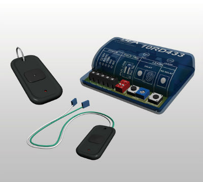
Bea 10rd433 433 Mhz Digital Receiver
Wiring diagrams sometimes called main or construc-tion diagrams show the actual connection points for the wires to the components and terminals of the controller.

10rd433 wiring diagram. Sort by 800390 - 10ACP12DS Access control package 5. Manuals Wiring Diagrams. 2 wire RTD connections The 2 wire RTD configuration is the simplest among RTD circuit designs.
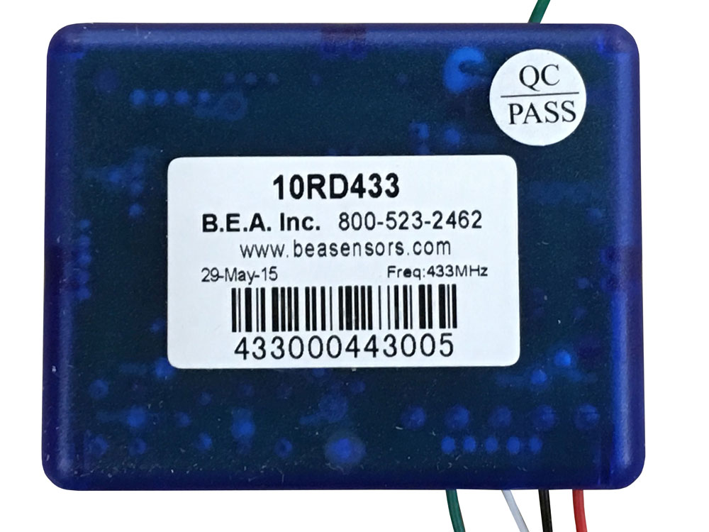
433 MHz digital receiver. 80042900 - Dynaco DY4000 Wiring To An LZR-Widescan. Download ASE-10RD433 Manual.
Pdf 21687 KB. BEA INC 10RD433 Wireless Receiver Digital 12 to 24 Volt ACDC 30 Milliampere 433 Megahertz 2125 Width x 275 Depth x 1 Height. Take the Tour.
7 - Factory Alarm Arm Output. 2 - Ignition Input. THERE IS A RISK OF EXPLOSION IF AN INCORRECT BATTERY.
-287 dBm TX Power Consumption. RTD wiring configurations There are three types of wire configurations 2 wire 3 wire and 4 wire that are commonly used in RTD sensing circuits. Getting Started IO Wiring and Specifications 3 4 IO Wiring and Specifications This next.
4 - Ignition 2 Input. 44 1 53850662 7822d005 labelfastraxfrwiring guide 42 2 55290009 mountcable tie1x1psa 43 1 16960001 conn cnd strt lt 1 not shown 45 1 53850663 7822d007 labelcvrtraxfrwiring guide expensed expensed if 30w power supply or 1 38120033 din raillow-profile9 activation option 53 12-24vacdc com no nc on 1 2 10rd433 12-24v acdc com. DL405 System AC Power Load Supply Input Supply Powering IO Circuits Using Separate Supplies.
Up to 100 Transmitters Can be Programmed into a Single. Camden has built our AVR exhibit just for you - with interactive menu options for demos literature and more. 3504 KB Views.
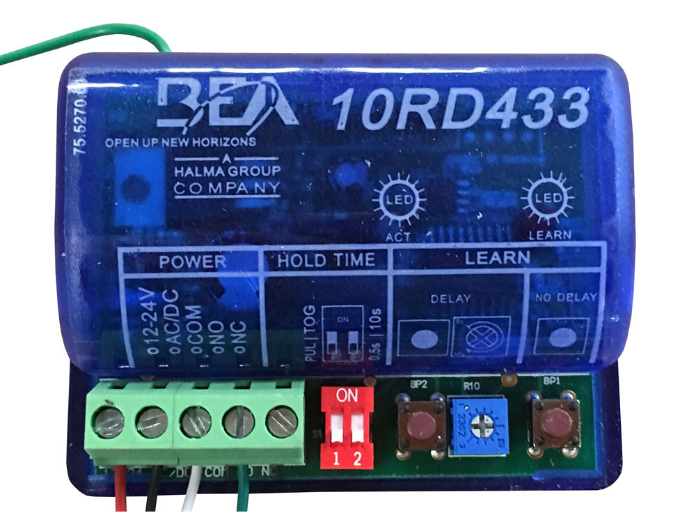
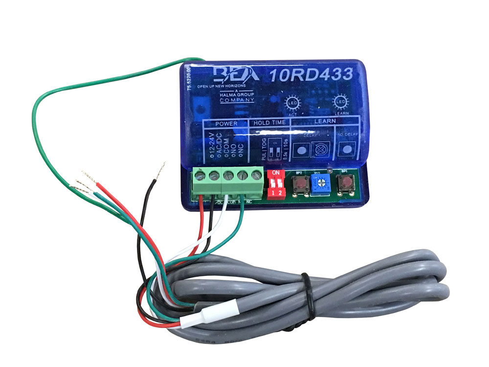
Does it look right. Wire Color Red Black - White Green Grey 1 2 Terminal Description Control or Transformer power 3 4 5 Control Common Control Activation Typically not used 6 Battery Replacement CAUTION. The example wiring diagram below on the right shows how this can work but also that the auxiliary supply output is an unused resource.
Manuals Wiring Diagrams. This page is dedicated to Wiring Diagrams that can hopefully get you through a difficult wiring task or just to learn some basics in how to wire a 2-way switch 3-way switch 4-way switch outlet or entertainment component diagramsIf you dont see a wiring diagram you are looking for on this page then check out my Sitemap page for more information you may find helpful. Up to 100 transmitters can be programmed into a single.
Product manuals user guides and spec sheets. Delay or No Delay Programming Options. Page 2 of 4 75509208 EN 20110217 5 Wiring Power VACDC Output Label 12 - 24 12 - 24 Com.
Pdf 10519 KB. Or send us an e-mail with your request to support. If you are having trouble locating the information you need call our helpful support team at 1-800-783-6112 between the hours of 8 am.
Here you will find free downloadable BEA Inc. BEA product documentation library containing product user guides cut sheets application notes architectural specifications wiring diagrams and brochures. 80043100 - Rytec System 4 Wiring To An LZR-Widescan.
Camden has built our AVR exhibit just for you - with interactive menu options for demos literature and more. MFR PART 10RD433. 10rd433 12-24v acdc com no nc pul tog 05s 10s delay no delay power hold time learn act learn 46 46 1 67850177 scrground10-32x38 and 1 53850048 labelground htr htr dc power consumption 22w.
12 to 24. AutoShift 18-Speed Wiring Diagram with Push Button Shifter. Wiring diagram The diagram below lists the wires that are common to most of the vehicle installations.
3 x 2 x 1 For use with the Panther Series of wireless push plates by BEA. All wires are 18 awg blue unless otherwise. Pdf 21697 KB.
7 White 8 thick-gauge wires 4 White Ignition Output. Mar 27 2014 2 bump. 3mA TX 30mA RX Input Voltage.
5 - Active When Armed. Looking to simplify my wiring. Typical Wiring Diagram Line.
80043000 - Rytec System 4 Wiring To An IS40. Description Product Resources BEA 10RD433 The BEA 10RD433 is a 433 MHz receiver that is universally compatible with any type of automatic door application. 4541 KB Views.
Optional preannounce relay wiring preannounce relay 24vac power incoming power from end user supplied disconnect notes. 3-Part Project Specifications System CAD Drawings Design Guides Studies. A 2-wire configuration with a compensating loop is also an option.
3-Part Project Specifications System CAD Drawings Design Guides Studies. They show the relative location of the components. Attached are two diagrams - one that was simplified and the original.
Integral sequencing learn buttons for vestibule sequencing Pulsetoggle functionality. Wiring Diagram Book A1 15 B1 B2 16 18 B3 A2 B1 B3 15 Supply voltage 16 18 L M H 2 Levels B2 L1 F U 1 460 V F U 2 L2 L3 GND H1 H3 H2 H4 F U 3 X1A F U 4 F U 5 X2A R Power On Optional X1 X2115 V 230 V H1 H3 H2 H4 Optional Connection Electrostatically Shielded Transformer F U 6 OFF ON M L1 L2 1 2 STOP OL M START 3 START START FIBER OPTIC TRANSCEIVER CLASS 9005 TYPE FT. They can be used as a guide when wiring the controller.
6542 The_Stache Been Around the Block. 1 - Starter Input. Eastern time Monday through Friday.
MFR PART 10RD433. 1 UltraShift DM3 6-Speed Wiring Diagram with Analog Shifter UltraShift DM3 6-Speed Wiring Diagram with Analog Shifter Gear select motor Rail select motor Electric shifter A B A B Rail select sensor Gea r10 select sensor Input shaft speed sensor Output shaft. Mar 30 2014 3 What are we reviewing.
3 - Accessory Input. In this serial configuration a single lead wire connects each end of the RTD element.
Bea 10rd433 433 Mhz Digital Receiver
Bea Jmac Supply
![]()
Bea 433 Mhz Frequency Digital Receiver For Panther Push Plates 10rd433

Bea 10rd433 433 Mhz Digital Receiver
Td433 433 Mhz Digital Transmitter User Manual Manual Bureau D Electronique Appliquee B E A

Bea 75 5839 03 Banner Wiring Diagram Led Signal Column Lights

Bea 10rd900 Commercial Receiver Console 900 Mhz For Door Openers And Push Plates

Bea 433 Mhz Frequency Digital Receiver For Panther Push Plates 10rd433
Bea 10rd433 433 Mhz Digital Receiver
Https Www Ritehite Com En Am Resource Center Manuals E6c3aaf5539a475ca2acbc5930cdf88a Previous Fastrax Fr Ld Owners Manual

Bea 10rd900 Commercial Receiver Console 900 Mhz For Door Openers And Push Plates
Bea 10rd433 433 Mhz Digital Receiver

Bea 10rd433 433 Mhz Digital Receiver Youtube

Bea 10rd900 Commercial Receiver Console 900 Mhz For Door Openers And Push Plates

Bea 10rd433 433 Mhz Digital Receiver
Td433 433 Mhz Digital Transmitter User Manual Manual Bureau D Electronique Appliquee B E A

Bea 10rd900 Commercial Receiver Console 900 Mhz For Door Openers And Push Plates
10td433 Remote Controller User Manual 75 5092 05 20070827 Rf433 Transmitters Indd Bureau D Electronique Appliquee B E A

Br3 Rd433 Non Ul Manualzz
Post a Comment for "10rd433 Wiring Diagram"