12v Battery Charger Bridge Rectifier Wiring Diagram
This circuit is designed to provide charging. This circuit can be used to charge all type of 12V rechargeable batteries including car batteries.

Pin On Detalles Electronicos
Wiring View and Schematics Diagram.

12v battery charger bridge rectifier wiring diagram. This circuit will eliminate the problems by monitoring the batterys condition of charge through its retroactive control. Most of the. Solar Octane Series Wheel Battery Chargers.
Us 240 0 St32c Thyristor Control Board Scr Firing Card Bridge Rectifier Controller 3 Phase In Voltage Regulators Stabilizers From Home. 12v bridge rectifier circuit diagram December 31 2020. Since there is D3 in the path to battery under 1.
Battery Charger Transformer Wiring Diagram. Yes you need a rectifier. The circuit is nothing but a 12V DC power supply with an ammeter for monitoring the charging current.
The first stage of the circuit is a transformer which is a step-down type that changes the amplitude of the input voltage. Can this go direct to the side of the battery or does it need to be through the switched power source to prevent any type of draw with. If the battery is partially discharged full charge will be attained in one hour.
Remembering the proper layout of diodes in a full-wave bridge rectifier circuit can often be frustrating to the new student of electronics. 1 shows the circuit of diode bridge rectifier. Thus during the first half cycle diodes D1 and D 3 are forward biased and current flows through arm AB enters the load resistance R L and.
This circuit can be used to charge all type of 12V rechargeable batteries including car batteries. By the way 12V trafo ac gives about 168V dc 1214 that goes in to lm317. The above circuit claimed have ability to prevent battery overcharge that make electrolyte lost due to evaporation.
12v Battery Charger. Also I need to instal a rectifier to charge my battery. Full Wave Bridge Rectifier Circuit Diagram Full Wave.
It is generally made up of diode switches as shown in Circuit Diagram. 61d4 Diode Bridge Rectifier Wiring Diagram For Wiring. This 12v battery charger Automatic cut circuit after a full charge and provides 6 Ampere high current and this can use for a big size Lead-acid Battery up to 100 AH.
I am wiring this GT-14 with a new switch from iSaveTractors. I realized there is no provision on the switch for the charging wire from the regulatorrectifier. Either a regulator for lighting or charging rectifier kit for DC battery charging.
The circuit uses a 0-14 volt 5 Ampere Step down transformer and a 10 Amps Bridge rectifier module to convert AC to DC. 2 of the 4 diodes are not used in bridge rectifier I mean they are there to prevent voltage from running the wrong way. The capacitor filters the.
Battery charger circuit diagram with parts list. Step by step test of rectifier plate on an automotive batter charger. The circuit is assembled following conventional steps of power.
During the first half cycle. 12 Volt Battery Charger Wiring Diagram wiring diagram is a simplified within acceptable limits pictorial representation of an electrical circuit. In that case the dome light will remain on all night and the battery.
The bridge rectifier circuit diagram consists of various stages of devices like a transformer Diode Bridge filtering and regulators. 30V When it converts to DCV. Rectifier circuit is a converter which converts ac supply in to dc supply.
The two diodes forms a centre tapped full wave rectifier. I simply glued the bridge rectifier to the plywood with hot glue. 12v battery charger bridge rectifier wiring diagram.
Here is the complete circuit diagram for cell phone charger circuit. This is the circuit of a simple 12 volt battery charger for Lead Acid battery. Full Wave Bridge Rectifier Circuit Diagram with Input and Output Wave Forms.
Full wave bridge rectifier circuit diagram design the last 12v ac to 12vdc with simple. To convert ac into dc we can make two types of rectifiers one is half. Off Switch C1 10uF 25V GR1 50V 6A Bridge Rectifier F 5A Fuse.
Step II. Here is the circuit diagram of a simple and straight forward 12 V battery charger circuit with diagram. Is anyone know the wiring diagram for this rectifier.
Taming The Lm3886 Rectification And Snubbers Neurochrome. This area is a growing library of the schematics wiring diagrams and technical photos. If you want to more high current then replace the transformer with 10A and use 10A10 Diode.
Ac To Dc Bridge Rectifier Circuit Diagram Posted by Margaret Byrd Posted on May 29 2018. 5pcs 50a Kbpc5010 1000v Metal Case Single Phases Diode Bridge. Lm317 takes 3V to itself check datasheet so the whole circuit uses around 138-14V.
Full Wave Rectifier Bridge Rectifier Circuit Diagram With. Bridge rectifier gives the same output as this rectifier. Auto Battery Charger for 6 or 12 Volt Sytems.
This circuit can change the battery voltage of 3 sizes 6V 9V 12V. Diode Bridge Rectifier Wiring Diagram For Wiring Schematic. Generally all these blocks combination is called a regulated DC power supply that powers various electronic appliances.
You can use a readymade 12v 10 A Bridge Rectifier which is available in the market. Diodes 1N4007 x 3 1N4732A Zener 2SD882 NPN. It shows the components of the circuit as simplified shapes and the faculty and signal associates between the devices.
These Alternator Kits are used to provide 12V power for manual start models. 1966 Ford Fairlane Wiring Diagram Related Post 12v Portable Battery Charger Circuit using LM317. Although Im aware.
Here is a simple and easy to build circuit diagram of a 12V car battery charger. 12 Volt 10 Amp Transformer Battery Charger Circuit DiagramFor More Information Visit our Site. It is handy to have a small battery charger for your automobile especially if someone parks it in your garage for the night with a door just slightly ajar.
In a normal circuit we use with 12V battery. The manual says this oulet will produce 80 watts at 12 volts. It gives 12 volt and 5 Amps current for quick charging of the battery.
Converting 12v AC into 12v DC using Full Bridge Rectifier. During the first half cycle of the input voltage the upper end of the transformer secondary winding is positive with respect to the lower end. The outer two terminals of the centre tapped transformer are connected to the bridge rectifier circuit.

Pin On Power Supply Ayarli Guc Kaynagi

Reconditioned Batteries For Sale Near Me Batteryreconditioningscam Id 1208338897 Batterycharger Battery Charger Circuit Battery Circuit

Ac To Dc Using Bridge Diode And Capacitor Bridge Rectifier Youtube Diode Capacitor Ac Capacitor

Pin En Battery Charging

Kbpc5010 Bridge Rectifier Wiring Diagram Further Pont De Diode Large Choix De Produits A Decouvrir Together With Bridge Rectifier Schematic

Pin On Electronics

Pin On Places To Visit

Automatic 12v Battery Charger With Explanation Automatic Battery Charger Battery Charger Diy Amplifier

Pin On Electronics
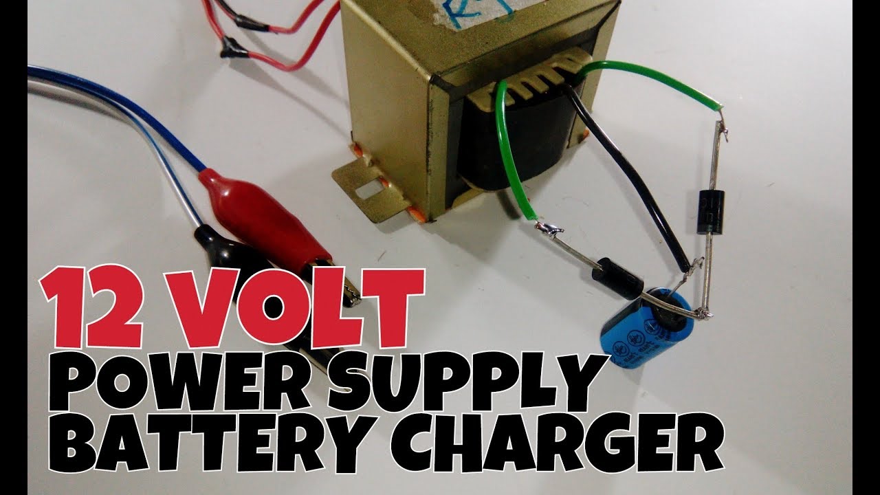
12 Volt Power Supply Battery Charger Half Bridge Rectifier Youtube Battery Charger Charger Power

Circuit Diagram Of Rectifier And 7812 12v Power Regulator Circuit Diagram Pic Microcontroller Home Automation
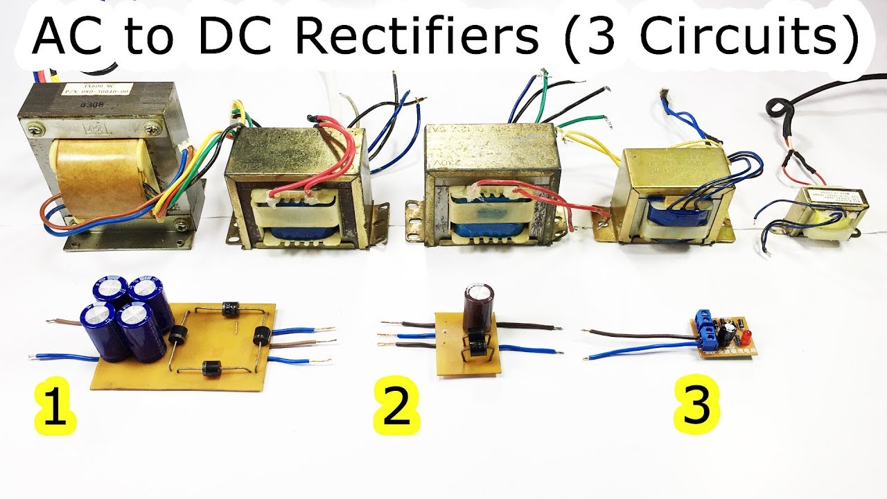
Ac To Dc Using Bridge Diode And Capacitor Half Wave Full Wave Bridge Rectifier 12v Center Tapped Youtub Acdc Electrical Circuit Diagram Electronics Projects

Pin On Motors
How To Make 12v Battery Charger At Home Youtube Charger Battery Charger 12v Solar Battery Charger

Variable Surge Free High Current Transformerless Power Supply Circuit Homemade Circuit Projects Power Supply Design Power Supply Circuit Circuit Projects

Battery Desulfator With Charger Circuit Using A Bridge Rectifier Batterycharger Battery Charger Circuit Electronic Circuit Projects Circuit Projects

Pin On Battery Power

220vac To 9vdc Regulated Power Supply Using Lm7805ct Bridge Rectifier 3n248 Power Supply Circuit Voltage Regulator Power Supply

Pin On Electronic
Post a Comment for "12v Battery Charger Bridge Rectifier Wiring Diagram"